Element Load Coordination System Example
The Loads.UniformLoad have a property named CoordinationSystem of enum type BriefFiniteElementNet.CoordinationSystem which defines the coordination system of load (for more info see Coordination System).
Using the combination of UniformLoad.CoordinationSystem and UniformLoad.Direction property, some specific distributed loads can be applied to elements.
Here are two examples:
Example 1
Consider the inclined frame shown in fig below, under dead load.
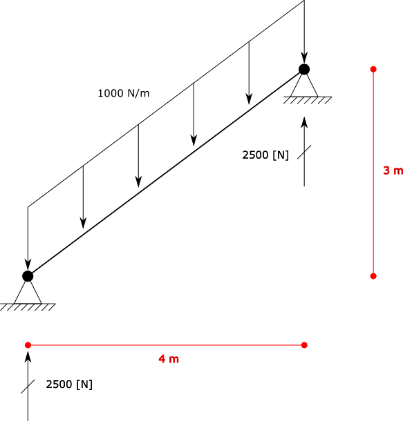
There is an inclined element of length = 5 [m], and an UniformLoad of magnitude 1000 [N/m].
Magnitude of 1000 [N/m]
Direction of Z
Coordination System of Global
step 1: create model, nodes and elements:
var m1 = new Model();

var el1 = new BarElement();

el1.Nodes[0] = new Node(0, 0, 0) { Constraints = Constraints.MovementFixed & Constraints.FixedRX, Label = "n0" };
el1.Nodes[1] = new Node(3, 0, 4) { Constraints = Constraints.MovementFixed, Label = "n1" };

el1.Section = new Sections.UniformGeometric1DSection(SectionGenerator.GetISetion(0.24, 0.67, 0.01, 0.006));
el1.Material = UniformIsotropicMaterial.CreateFromYoungPoisson(210e9, 0.3);


var l1 = new Loads.UniformLoad();

l1.Direction = Vector.K;
l1.CoordinationSystem = CoordinationSystem.Global;
l1.Magnitude = 1e3;


el1.Loads.Add(l1);

m1.Elements.Add(el1);
m1.Nodes.Add(el1.Nodes);

m1.Solve_MPC();

Console.WriteLine("n0 reaction: {0}", m1.Nodes[0].GetSupportReaction());
Console.WriteLine("n1 reaction: {0}", m1.Nodes[0].GetSupportReaction());
result
n0 reaction: F: 0, 0, -2500, M: 0, 0, 0 n1 reaction: F: 0, 0, -2500, M: 0, 0, 0
Example 2
Consider the inclined frame shown in fig below, under wind load.
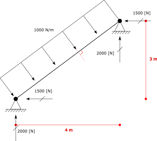
There is an inclined element of length = 5 [m], and an UniformLoad of magnitude 1000 [N/m].
Magnitude of 1000 [N/m]
Direction of Z
Coordination System of Local
var m1 = new Model();

var el1 = new BarElement();

el1.Nodes[0] = new Node(0, 0, 0) { Constraints = Constraints.MovementFixed & Constraints.FixedRX, Label = "n0" };
el1.Nodes[1] = new Node(3, 0, 4) { Constraints = Constraints.MovementFixed, Label = "n1" };

el1.Section = new Sections.UniformGeometric1DSection(SectionGenerator.GetISetion(0.24, 0.67, 0.01, 0.006));
el1.Material = UniformIsotropicMaterial.CreateFromYoungPoisson(210e9, 0.3);


var l1 = new Loads.UniformLoad();

l1.Direction = Vector.K;
l1.CoordinationSystem = CoordinationSystem.Local;
l1.Magnitude = 1e3;


el1.Loads.Add(l1);

m1.Elements.Add(el1);
m1.Nodes.Add(el1.Nodes);

m1.Solve_MPC();

Console.WriteLine("n0 reaction: {0}", m1.Nodes[0].GetSupportReaction());
Console.WriteLine("n1 reaction: {0}", m1.Nodes[0].GetSupportReaction());
result
n0 reaction: F: 2000, 0, -1500, M: 0, 0, 0
n1 reaction: F: 2000, 0, -1500, M: 0, 0, 0
Example 3
Consider the inclined frame shown in fig below, under snow load.
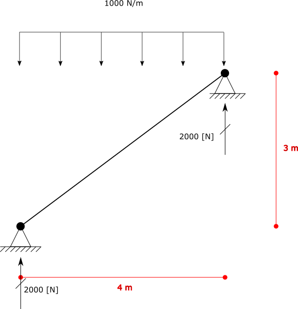
Projected Magnitude of 1000 [N/m]
Direction of Z
Coordination System of Global
There is an inclined element of length = 5 [m], and an UniformLoad of magnitude 1000 [N/m] which is projected.
There is a difference about this type of load with two other examples above. For applying such projected load, first we have to convert it to example 1.
Based on toturial in www.learnaboutstructures.com this is the way to convert:

So in this example we do not need theta value itself, but we need Cos(θ) or more precise absolute value of it |Cos(θ)|. Due to elementary trigonometry relations Cos(θ)=Sin(90°-θ). So instead of |Cos(θ)| we can calculate |Sin(α)| where α = 90°-θ and α equals to angle between load direction and element direction. For finding |Sin(α)| we can use length of cross product of two unit vectors of element direction and load direction. This coefficient is always a non negative value and less than or equal to 1.0. If element is horizontal then |Cos(θ)| = 1.0 if element is vertical then |Cos(θ)| = 0.0.
Hint
Note that actually two vectors have tow angles between them, a bigger one and a smaller one, but absolute value of cosine of them both are same i.e |Cos(θ)| = |Cos(180°-θ)|
var m1 = new Model()
var el1 = new BarElement();

el1.Nodes[0] = new Node(0, 0, 0) { Constraints = Constraints.MovementFixed & Constraints.FixedRX, Label = "n0" };
el1.Nodes[1] = new Node(4, 0, 3) { Constraints = Constraints.MovementFixed, Label = "n1" };

el1.Section = new Sections.UniformGeometric1DSection(SectionGenerator.GetISetion(0.24, 0.67, 0.01, 0.006));
el1.Material = UniformIsotropicMaterial.CreateFromYoungPoisson(210e9, 0.3);

var loadMagnitude = -1e3;
var loadDirection = Vector.K;

var l1 = new Loads.UniformLoad();

var elementDir = el1.Nodes[1].Location - el1.Nodes[0].Location;//or n0 - n1, does not matter

var absCosTeta = Vector.Cross(elementDir.GetUnit(), loadDirection.GetUnit()).Length;

l1.Direction = loadDirection;
l1.CoordinationSystem = CoordinationSystem.Global;
l1.Magnitude = loadMagnitude * absCosTeta; //magnitude should multiple by reduction coefficient absCosTeta

el1.Loads.Add(l1);

m1.Elements.Add(el1);
m1.Nodes.Add(el1.Nodes);

m1.Solve_MPC();

Console.WriteLine("n0 reaction: {0}", m1.Nodes[0].GetSupportReaction());
Console.WriteLine("n1 reaction: {0}", m1.Nodes[0].GetSupportReaction());
result
n0 reaction: F: 0, 0, 2000, M: 0, 0, 0 n1 reaction: F: 0, 0, 2000, M: 0, 0, 0
whole source code exists in the UniformLoadCoordSystem.cs file.